Stadiæ maintains an in-memory model of your diagram — states, choice-points, interfaces, messages, transitions — and re-emits PlantUML source from scratch on every edit. You never touch PlantUML syntax unless you want to; you edit behaviour. The server renders it; you see the result.
The domain is not decoration. The tool knows that a choice-point has exactly two branches (Yes / No), that an initial transition carries no message, that each source handles a given message at most once, that History and ANY are real pseudo-states with real semantics. Malformed diagrams cannot be saved, because they cannot be constructed.
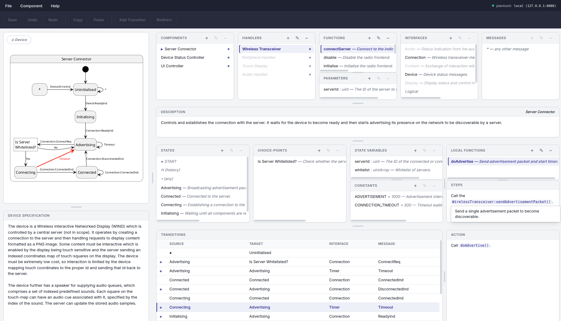
sample output · generated PlantUML
'== States ==
state Advertising
state Connecting
state CP_Whitelisted as "Is Server\nWhitelisted?"

'== Transitions ==
[*]            --> Advertising
Advertising    --> CP_Whitelisted    : $RTx_ConnectReq
CP_Whitelisted --> Connecting        : $Logical_Yes
CP_Whitelisted --> Error             : $Logical_No